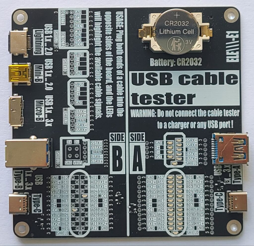
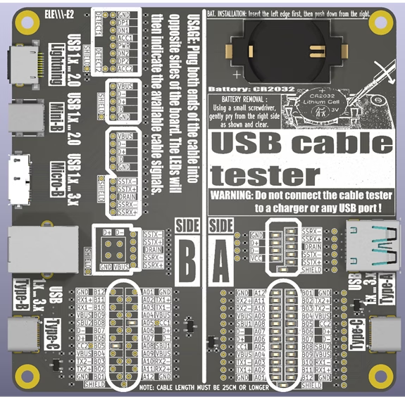
Here is our USB cable tester board.
User’s manual in English and Korean
USB Cable Tester – User’s Manual
🧭 Introduction
The USB Cable Tester is a diagnostic tool designed to verify internal wiring of various USB cables with minimum length of 12 inches or 30 centimeters. This manual provides instructions for use of the tester.
🔍 Overview
Power Source: CR2032 Lithium Cell (3V).
Purpose: Test pin continuity and identify passive USB cables.
🔌 Connector combinations supported:
A-side:
- Type-C
- Type-A / Type-A Super Speed
B-Side:
- Type-C
- Type-B / Type-B Super Speed
- Micro-B / Micro-B Super Speed
- Mini-B
- Lightning
It passively illuminates LEDs showing which signals (power, data, configuration, shield) are connected between the cable ends.
Board Layout
– Pin mapping LED matrices
– Label overlays for signal identification
– Test points for a USB cable pin to pin continuity tests
⚠️ WARNING: Before continuity tests with a multimeter the battery (CR2032) must be removed!
⚠️ Safety Warnings
- Use only with unpowered cables! DO NOT connect this tester to a USB charger, PC, or live USB host. Connecting the tester to a charger or active USB port may damage the device or cause injury.
- Keep out of reach of children. It is not a toy.
- Handle with Care: Avoid short-circuiting pins or exposing the board to moisture.
- The board is not designed to carry power or signals – it’s a passive tester.
📐 How to Use and Interpret Results
- Ensure the tester is powered by the CR2032 battery.
- Testing a Cable:
- Select the appropriate USB ports on the tester matching your cable type (e.g., Type-C to Type-C).
- Connect one end of the cable to a port on Side A.
- Connect the other end to the corresponding port on Side B.
- Interpreting Results:
- Visually inspect the LED indicators. Check for consistent pin connections (e.g., Power: VBUS, GND. Data: D+, D-…).
- Use the reference matrix (the tester board bottom side) to identify the cable.
- Once testing is complete, unplug both ends of the USB cable to preserve battery life.
💡 Understanding LED Indicators
- Each LED indicates the presence of a connected signal path through the cable, except for the configuration lines CC1 and CC2.
- LED ON = continuity exists on that line
- LED OFF = no connection on that line
- The CC1 and CC2 LEDs indicate the presence of pull-up resistors (Rp) built into the cable on the Downstream Facing Port (DFP) – typically the host:
- 56 kΩ (USB 2.0: 500mA, USB 3.x: 900mA)
- 22 kΩ (1.5A)
- 10 kΩ (3.0A)
The Rp resistor defines the advertised current to the Upstream Facing Port (UFP) – typically the device – which uses a 5.1 kΩ pull-down resistor (Rd). This combination forms voltage levels of approximately 0.66 V, 1.1 V or 1.7 V from a 5 V DC source.
- CC1 and CC2 connections in the Type-C to Type-C cables, as well as pin to pin shorts are not indicated by LEDs. These can be tested using a multimeter in continuity test mode.
⚠️ Refer to the battery removal warning mentioned above before testing.
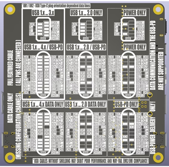
📘 Signal Reference Guide
| Signal | Description |
| VBUS | Bus power line |
| GND | Ground for power return |
| D+, D- | USB 2.0 data lines (One – unshielded twisted pair) |
| TX1+/-, RX1+/-, TX2+/-, RX2+/- | USB 3.x SuperSpeed lines (Four – shielded differential pairs) |
| CC1 / CC2 | Configuration channels (USB-PD) |
| SBU1 / SBU2 | Sideband use (USB-C) |
| Shield | Cable external braid |
The USB Type-C connector supports multiple standards, each with distinct signal configurations. Use the tester to verify the following essential signals:
USB 2.0 Data Cable:
Essential Signals: D+/- (Data +/-), VBUS (Power), GND (Ground).
Description: Supports data transfer up to 480 Mbps and power delivery up to 3A. Only uses two differential data pairs (D+ and D-).
USB 3.x Data Cable:
Essential Signals: USB 2.0 data cable signals plus TX+/-, RX+/- (SuperSpeed pairs).
Description: Supports data transfer up to 10 Gbps (USB 3.2 Gen 2) with additional SuperSpeed differential pairs.
USB-PD (Power Delivery) Cable:
Essential Signals: VBUS, GND, CC1/CC2 (Configuration Channels).
Description: Designed for power delivery up to 100W (20V, 5A) with dynamic voltage negotiation.
USB4 / Thunderbolt Cable:
Essential Signals: USB 3.x cable signals plus USB-PD signals plus TX1+/-, RX1+/-, TX2+/-, RX2+/- (Thunderbolt lanes), SBU1/2 (Sideband use).
Description: Supports data transfer up to 80 Gbps, video output, and power delivery. Verify all high-speed pairs and power lines.
📝 Notes
– Cables without shielding may still work but may fail EMC/EMI compliance requirements.
– Not all USB-C cables support all signals
🛠️ Troubleshooting
| Issue | Possible Cause | Solution |
| No LEDs light up | Battery dead or reversed | Replace or flip the battery |
| Some expected LEDs are off | Cable missing lines or is defective | Try a known-good cable |
| LEDs dim or flickering | Bad a USB port contacts | Try a known-good cable |
📊 Technical Specifications
– Power Source: CR2032 coin cell battery
– Maximum Battery Current: 8 mA
– Compatibility: USB-A/B/C, Micro/Mini-B, Lightning
– Test method: Passive continuity via LED
– Minimum Supported Cable Length: 25 cm
– Dimensions: 100mm x 100mm
Leave a Reply