Blog
-
1-channel analog isolator
User’s manual in English and Korean
📘 Specification & User Manual
Product Name: 1CH 5kV Analog Isolator Board
Model: 1CH-A-ISO
🔹 1. General Description
The 1CH 5kV Analog Isolator Board is designed to provide safe galvanic isolation between field analog signals and microcontroller systems. It supports temperature sensing, current loop interface (4–20mA), and voltage input signals (0–3.3V, 0–5V, 0–10V).
The board delivers a scaled and isolated analog output (0–3.3V or 0–5V) suitable for ADC inputs.An onboard RC low-pass filter can be configured to suppress noise with selectable cutoff frequencies: 10Hz, 100Hz, or 1kHz.
🔹 2. Features
- ✅ Input Interfaces:
- NTC temperature sensor input
- 4–20mA current loop input
- Voltage inputs: 0–3.3V, 0–5V, 0–10V
- ✅ Output Signal (Isolated):
- 0–3.3V or 0–5V (selectable by jumper)
- ✅ Galvanic Isolation:
- Up to 5kV RMS isolation voltage
- ✅ Noise Reduction:
- Selectable RC low-pass filter cutoff: 10Hz, 100Hz, 1kHz
- ✅ Power Supply:
- Power input (analog isolator output side): +5V DC / 300mA max
- Isolated Power output (Isolated input side): +5V DC / 200mA max
- ✅ Accuracy: ±1% FS typical
- ✅ Applications:
- Industrial process control
- Medical equipment
- Sensor isolation
- PLC/microcontroller signal interface
- Data acquisition
🔹 3. Electrical Specifications
Parameter Min Typ Max Unit Notes Isolation Voltage — 5 — kVrms Between input & output Input Current Range 4 — 20 mA Standard 4–20mA loop Input Voltage Range 0 — 10 V Selectable via jumper Output Voltage Range 0 — 3.3/5 V Selectable Power Supply Voltage 4.75 5.0 5.25 V Primary side Output Load Resistance 2k — — Ω Recommended Bandwidth (no filter) — 10k — Hz Typical Filter Cutoff Frequency 10 100 1k Hz Selectable Operating Temperature Range -20 — +70 °C — 🔹 4. Pinout Description
Power Input (Primary Side)
- +5VIN : +5V DC supply
- GND : Ground reference
Analog Input (Isolated Side)
- CURRENT : 4–20mA input
- VOLTAGE : 0–3.3V / 0–5V / 0–10V input
- NTC : Temperature sensor input
- +5VISO : Isolated +5V supply
- GNDISO : Isolated ground
Output (Non-Isolated Side)
- OUT : Isolated analog output (0–3.3V or 0–5V)
- GND : Output ground
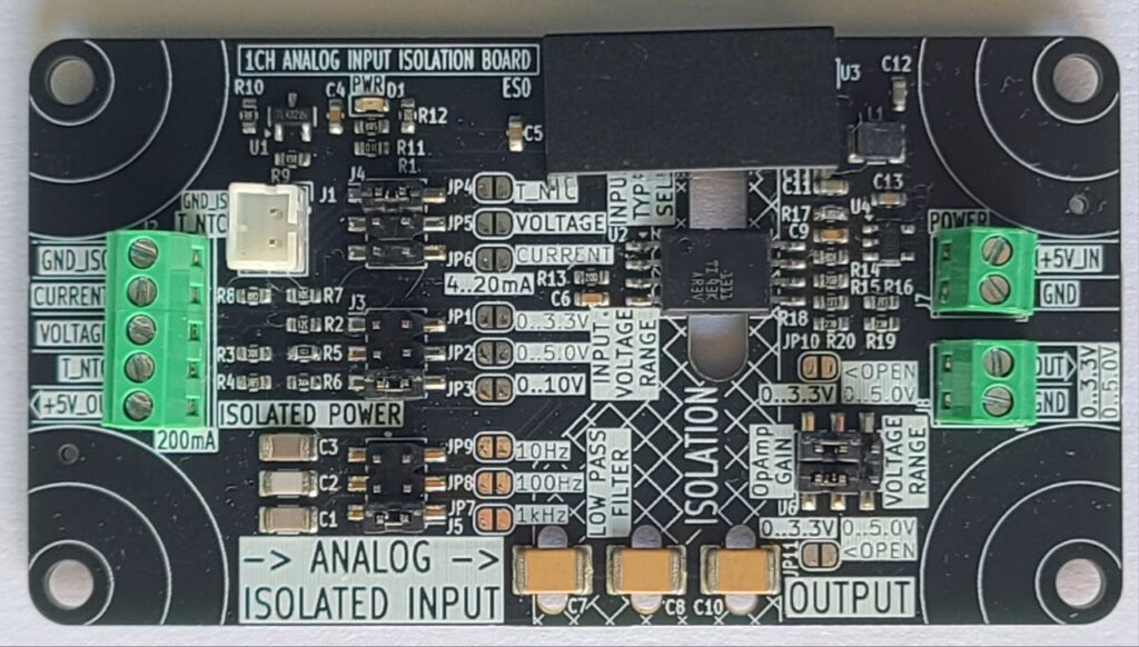
🔹 5. Configuration
- Input Range Selection: Set via jumpers (0–3.3V, 0–5V, 0–10V, 4–20mA, NTC).
- Output Range Selection: Set via jumper (0–3.3V or 0–5V).
- Filter Selection: Jumper to select cutoff frequency:
- JP1 → 10Hz
- JP2 → 100Hz
- JP3 → 1kHz
🔹 6. Example Applications
- Temperature Monitoring: Connect an NTC sensor to the input, read isolated voltage output with MCU ADC.
- Industrial Process Control: Receive 4–20mA loop signal from transmitter, output isolated 0–5V for PLC ADC.
- Noise-Sensitive Systems: Enable 10Hz filter for stable readings.
- High-Speed Control: Use 1kHz filter for fast response applications.
🔹 7. Safety Notes
- Ensure correct input range is configured before connecting signals.
- Do not exceed 10V input or 20mA current input.
- Maintain isolation gap between high-voltage field wiring and control side.
Comments
- ✅ Input Interfaces:
-
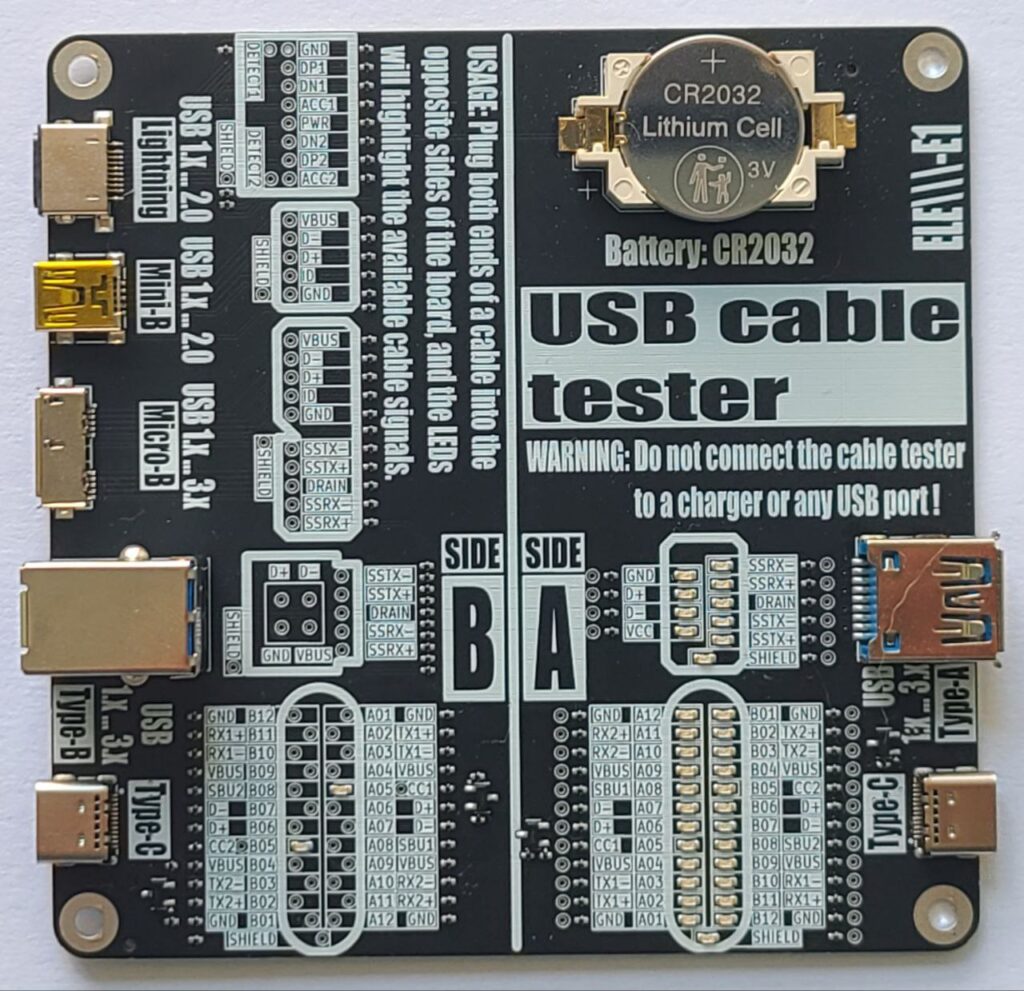
USB Cable Tester
Here is our USB cable tester board.
User’s manual in English and Korean
USB Cable Tester – User’s Manual
🧭 Introduction
The USB Cable Tester is a diagnostic tool designed to verify internal wiring of various USB cables with minimum length of 12 inches or 30 centimeters. This manual provides instructions for use of the tester.
🔍 Overview
Power Source: CR2032 Lithium Cell (3V).
Purpose: Test pin continuity and identify passive USB cables.
🔌 Connector combinations supported:
A-side:
- Type-C
- Type-A / Type-A Super Speed
B-Side:
- Type-C
- Type-B / Type-B Super Speed
- Micro-B / Micro-B Super Speed
- Mini-B
- Lightning
It passively illuminates LEDs showing which signals (power, data, configuration, shield) are connected between the cable ends.
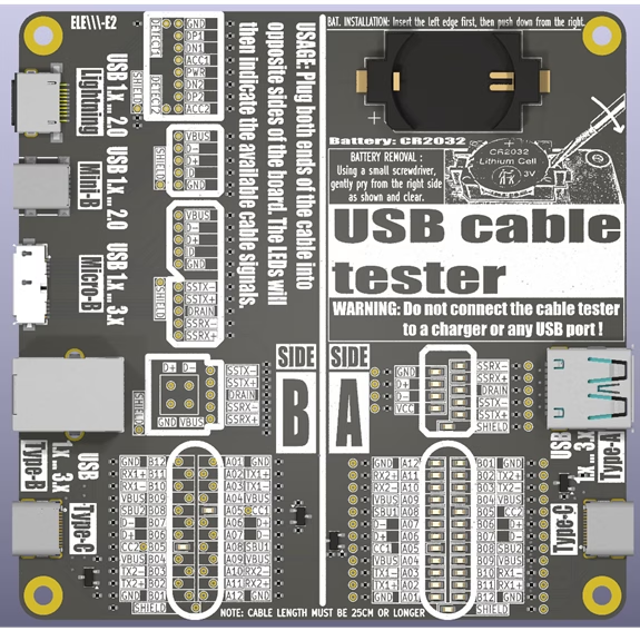
Board Layout
– Pin mapping LED matrices
– Label overlays for signal identification– Test points for a USB cable pin to pin continuity tests
⚠️ WARNING: Before continuity tests with a multimeter the battery (CR2032) must be removed!
⚠️ Safety Warnings
- Use only with unpowered cables! DO NOT connect this tester to a USB charger, PC, or live USB host. Connecting the tester to a charger or active USB port may damage the device or cause injury.
- Keep out of reach of children. It is not a toy.
- Handle with Care: Avoid short-circuiting pins or exposing the board to moisture.
- The board is not designed to carry power or signals – it’s a passive tester.
📐 How to Use and Interpret Results
- Ensure the tester is powered by the CR2032 battery.
- Testing a Cable:
- Select the appropriate USB ports on the tester matching your cable type (e.g., Type-C to Type-C).
- Connect one end of the cable to a port on Side A.
- Connect the other end to the corresponding port on Side B.
- Interpreting Results:
- Visually inspect the LED indicators. Check for consistent pin connections (e.g., Power: VBUS, GND. Data: D+, D-…).
- Use the reference matrix (the tester board bottom side) to identify the cable.
- Once testing is complete, unplug both ends of the USB cable to preserve battery life.
💡 Understanding LED Indicators
- Each LED indicates the presence of a connected signal path through the cable, except for the configuration lines CC1 and CC2.
- LED ON = continuity exists on that line
- LED OFF = no connection on that line
- The CC1 and CC2 LEDs indicate the presence of pull-up resistors (Rp) built into the cable on the Downstream Facing Port (DFP) – typically the host:
- 56 kΩ (USB 2.0: 500mA, USB 3.x: 900mA)
- 22 kΩ (1.5A)
- 10 kΩ (3.0A)
The Rp resistor defines the advertised current to the Upstream Facing Port (UFP) – typically the device – which uses a 5.1 kΩ pull-down resistor (Rd). This combination forms voltage levels of approximately 0.66 V, 1.1 V or 1.7 V from a 5 V DC source.
- CC1 and CC2 connections in the Type-C to Type-C cables, as well as pin to pin shorts are not indicated by LEDs. These can be tested using a multimeter in continuity test mode.
⚠️ Refer to the battery removal warning mentioned above before testing.
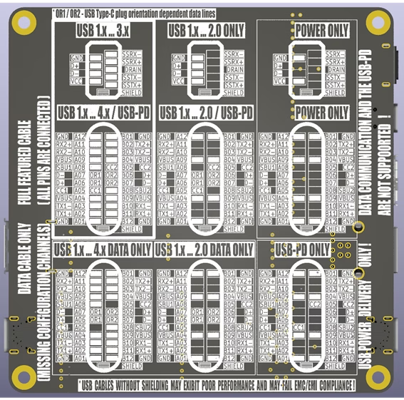
📘 Signal Reference Guide
Signal Description VBUS Bus power line GND Ground for power return D+, D- USB 2.0 data lines (One – unshielded twisted pair) TX1+/-, RX1+/-, TX2+/-, RX2+/- USB 3.x SuperSpeed lines (Four – shielded differential pairs) CC1 / CC2 Configuration channels (USB-PD) SBU1 / SBU2 Sideband use (USB-C) Shield Cable external braid The USB Type-C connector supports multiple standards, each with distinct signal configurations. Use the tester to verify the following essential signals:
USB 2.0 Data Cable:
Essential Signals: D+/- (Data +/-), VBUS (Power), GND (Ground).
Description: Supports data transfer up to 480 Mbps and power delivery up to 3A. Only uses two differential data pairs (D+ and D-).
USB 3.x Data Cable:
Essential Signals: USB 2.0 data cable signals plus TX+/-, RX+/- (SuperSpeed pairs).
Description: Supports data transfer up to 10 Gbps (USB 3.2 Gen 2) with additional SuperSpeed differential pairs.
USB-PD (Power Delivery) Cable:
Essential Signals: VBUS, GND, CC1/CC2 (Configuration Channels).
Description: Designed for power delivery up to 100W (20V, 5A) with dynamic voltage negotiation.
USB4 / Thunderbolt Cable:
Essential Signals: USB 3.x cable signals plus USB-PD signals plus TX1+/-, RX1+/-, TX2+/-, RX2+/- (Thunderbolt lanes), SBU1/2 (Sideband use).
Description: Supports data transfer up to 80 Gbps, video output, and power delivery. Verify all high-speed pairs and power lines.
📝 Notes
– Cables without shielding may still work but may fail EMC/EMI compliance requirements.
– Not all USB-C cables support all signals🛠️ Troubleshooting
Issue Possible Cause Solution No LEDs light up Battery dead or reversed Replace or flip the battery Some expected LEDs are off Cable missing lines or is defective Try a known-good cable LEDs dim or flickering Bad a USB port contacts Try a known-good cable 📊 Technical Specifications
– Power Source: CR2032 coin cell battery
– Maximum Battery Current: 8 mA
– Compatibility: USB-A/B/C, Micro/Mini-B, Lightning
– Test method: Passive continuity via LED
– Minimum Supported Cable Length: 25 cm– Dimensions: 100mm x 100mm
Leave a Reply
Leave a Reply