User’s manual in English and Korean
📘 Specification & User Manual
Product Name: 1CH 5kV Analog Isolator Board
Model: 1CH-A-ISO
🔹 1. General Description
The 1CH 5kV Analog Isolator Board is designed to provide safe galvanic isolation between field analog signals and microcontroller systems. It supports temperature sensing, current loop interface (4–20mA), and voltage input signals (0–3.3V, 0–5V, 0–10V).
The board delivers a scaled and isolated analog output (0–3.3V or 0–5V) suitable for ADC inputs.
An onboard RC low-pass filter can be configured to suppress noise with selectable cutoff frequencies: 10Hz, 100Hz, or 1kHz.
🔹 2. Features
- ✅ Input Interfaces:
- NTC temperature sensor input
- 4–20mA current loop input
- Voltage inputs: 0–3.3V, 0–5V, 0–10V
- ✅ Output Signal (Isolated):
- 0–3.3V or 0–5V (selectable by jumper)
- ✅ Galvanic Isolation:
- Up to 5kV RMS isolation voltage
- ✅ Noise Reduction:
- Selectable RC low-pass filter cutoff: 10Hz, 100Hz, 1kHz
- ✅ Power Supply:
- Power input (analog isolator output side): +5V DC / 300mA max
- Isolated Power output (Isolated input side): +5V DC / 200mA max
- ✅ Accuracy: ±1% FS typical
- ✅ Applications:
- Industrial process control
- Medical equipment
- Sensor isolation
- PLC/microcontroller signal interface
- Data acquisition
🔹 3. Electrical Specifications
| Parameter | Min | Typ | Max | Unit | Notes |
| Isolation Voltage | — | 5 | — | kVrms | Between input & output |
| Input Current Range | 4 | — | 20 | mA | Standard 4–20mA loop |
| Input Voltage Range | 0 | — | 10 | V | Selectable via jumper |
| Output Voltage Range | 0 | — | 3.3/5 | V | Selectable |
| Power Supply Voltage | 4.75 | 5.0 | 5.25 | V | Primary side |
| Output Load Resistance | 2k | — | — | Ω | Recommended |
| Bandwidth (no filter) | — | 10k | — | Hz | Typical |
| Filter Cutoff Frequency | 10 | 100 | 1k | Hz | Selectable |
| Operating Temperature Range | -20 | — | +70 | °C | — |
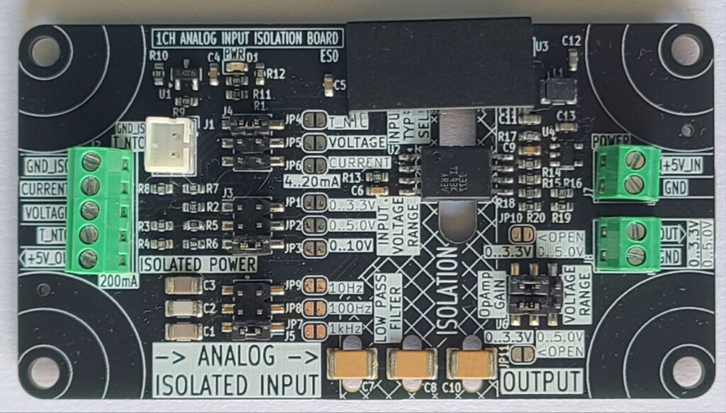
🔹 4. Pinout Description
Power Input (Primary Side)
- +5VIN : +5V DC supply
- GND : Ground reference
Analog Input (Isolated Side)
- CURRENT : 4–20mA input
- VOLTAGE : 0–3.3V / 0–5V / 0–10V input
- NTC : Temperature sensor input
- +5VISO : Isolated +5V supply
- GNDISO : Isolated ground
Output (Non-Isolated Side)
- OUT : Isolated analog output (0–3.3V or 0–5V)
- GND : Output ground
🔹 5. Configuration
- Input Range Selection: Set via jumpers (0–3.3V, 0–5V, 0–10V, 4–20mA, NTC).
- Output Range Selection: Set via jumper (0–3.3V or 0–5V).
- Filter Selection: Jumper to select cutoff frequency:
- JP1 → 10Hz
- JP2 → 100Hz
- JP3 → 1kHz
🔹 6. Example Applications
- Temperature Monitoring: Connect an NTC sensor to the input, read isolated voltage output with MCU ADC.
- Industrial Process Control: Receive 4–20mA loop signal from transmitter, output isolated 0–5V for PLC ADC.
- Noise-Sensitive Systems: Enable 10Hz filter for stable readings.
- High-Speed Control: Use 1kHz filter for fast response applications.
🔹 7. Safety Notes
- Ensure correct input range is configured before connecting signals.
- Do not exceed 10V input or 20mA current input.
- Maintain isolation gap between high-voltage field wiring and control side.
Leave a Reply